22 of the most immodest masterpieces of painting. Shocking masterpieces of classical painting
Federal Agency for Education
State educational institution higher
vocational education
"Ufa State Oil Technical University»
Department: “Transport and storage of oil and gas”
on the topic: “Types of shut-off valves, their purpose and design”
Completed by: student of group GRz-07-02
Politaev M.A.
Checked by: teacher
Fazletdinov R.A.
Shut-off valves- designed to completely shut off the flow of the working medium in the pipeline and start the medium depending on the requirements of the technological process (open-close cycle). This includes gate valves, taps, shut-off valves, and butterfly valves. The main purpose of shut-off and control valves is to shut off the flow of the working medium through the pipeline and let the medium in again, as well as to ensure the necessary tightness. The pipeline fittings plant monitors the quality of its products. The fittings are installed on high and low pressure pipelines, units and vessels. Shut-off valves are designed to control: water, gaseous, vapor, gas-liquid mass by changing the area of the diameter of the opening. It must ensure reliable and complete overlap of the flow area. In principle, it should provide only two states - open or closed - and may not be intended for operation in an intermediate position of the working body.
According to their functional purpose, pipeline fittings are divided into the following main classes:
Shut-off valve - designed to shut off the flow of the working medium with a certain tightness;
Regulating - designed to regulate flow by changing the amount of working medium flowing through the pipeline. The control valves are controlled from an external energy source;
Distribution - designed to distribute the flow of the working medium across certain directions or for mixing streams;
Safety - designed to automatically protect equipment and pipelines from unacceptable excess pressure by discharging excess working fluid., protective (cut-off) designed to automatically protect equipment and pipelines from unacceptable or unforeseen technological process changes in parameters or direction of flow of the working fluid, as well as to shut off the flow .
Phase separation - designed for automatic separation of working media depending on their phase and condition. These include steam traps, air vents and oil separators.
Gate valve– one of the shut-off valve devices. Here, unlike taps, the shut-off element does not perform a rotational movement, but a reciprocating one. The movement of the locking element occurs perpendicular to the movement of the liquid.
Chronologically, valves appeared as one of the first devices to shut off water flow. This is due to their sufficient simplicity and unpretentiousness in operation and repair. At present, due to the rapid development of technology and technological processes, valves are increasingly being replaced when laying pipelines by water shut-off devices with a circular movement of the actuator. Gate valves, like shut-off valves, are used mainly in two modes: open and closed, i.e. when the shut-off element is in its extreme positions. When using a valve in an intermediate position, its working surface is destroyed due to vibration caused by high-frequency movement of the actuator along and across the flow of liquid as it moves through the pipeline. The fastening elements of the actuator also become loose. As a result, the valve fails ahead of schedule.
Valves are divided into several types. Wedge, parallel, with retractable and non-retractable stem. They are used at pressures from 2 to 200 atmospheres. Nominal diameter from 8 mm to 2 m.
Figure 1 Gate valve ZMS-65-14 K1 HL (Baku)
Table 1 Specifications valves ZMS-65-14 K1 HL
Christmas tree fittings designed for sealing wellheads, monitoring and regulating their operating mode, as well as for carrying out various technological operations in temperate and cold macroclimatic regions for environments containing CO2, H2S, and formation water. Assembled according to tee and cross type schemes in accordance with GOST 13846 - 84.
The following designations are adopted in the code for the Christmas tree fixtures: AF – Christmas tree fittings; design according to GOST 13846 – 84 schemes; a – double-row concentric suspension of lifting pipes; K – suspension of the lifting string on the thread of the pipe head sub (the letter is not written on the coupling suspension); E – for operating wells with ESP; B – method of valve control (remote and automatic); the first number is the nominal diameter of the barrel and side strings in mm; the second number is the working pressure; HL – climatic version for cold areas; corrosion resistance version: K1 – for environments containing CO2 up to 6%; K2 – for environments containing CO2 up to 6%; K3 – the same, H2S and CO2 up to 25%; K2I - for Christmas tree equipment made of low-alloy and low-carbon steel, using an inhibitor in the well.
The fittings include a pipe head, a fountain tree, shut-off devices with manual and pneumatic control, and chokes.
The pipe head is designed for hanging one or two rows of tubing, sealing them, as well as for performing technological operations during the development, operation and repair of a well.
The riser pipe columns are suspended on threads and coupling suspensions.
Hanging of columns on the thread is carried out: with a single-row elevator - on the thread of the stem coil; with a two-row elevator: the inner column is on the thread of the stem coil, the outer column is on the thread of the tee (cross) of the pipe head.
Hanging of columns on a coupling suspension is carried out: with a single-row elevator - on a coupling in the crosspiece of the pipe head; with a two-row elevator: internal - on the coupling in the tee of the pipe head, external - on the coupling in the cross.

Figure 2 Christmas tree fittings AFK 1 E65x21M K1 HL
(for ESP, RPM and flowing wells)
The tree is designed to direct well production to the flow line for regulating the operating mode, for installing special devices when lowering downhole tools or pigs to clean paraffin from pipes, measuring pressure and temperature of the medium, as well as for carrying out some technological operations.
Continuous plug valves and direct-flow valves with forced or automatic supply of lubricant are used as shut-off devices for Christmas tree fittings. They are designed to cover flow holes in Xmas trees and wellhead equipment.
Table 2 Technical characteristics of the Christmas tree fittings AFK 1 E65x21M K1 HL
To regulate the operating mode, adjustable or non-adjustable throttles with a replaceable bushing made of wear-resistant material are installed on the side strings of the tree.
Christmas tree fittings are classified according to their design and strength characteristics:
Working pressure (7, 14, 21, 35, 70, 105 MPa);
Execution scheme (6 schemes);
The number of rows of pipes lowered into the well;
Designs of locking devices;
The dimensions of the flow section along the wellbore (50-150 mm) and side branches (50-100 mm).
All Christmas trees are used with column heads OOK1 10"" ´ 9 5/8 ´ 6 5/8 - 210 or column heads designed by TsNIL "" GANG "".
Column heads, like casing pipes, are an integral part of the well design as an engineering structure. They are designed to suspend the next casing string, seal and control the pressure in the annular space between adjacent pipe strings.

Figure 3 Column head piping OKK1-35 K1 HL
The design of the column head, Christmas tree fittings, and their piping schemes must ensure optimal well operating conditions, sealing of the pipe, annular and annular spaces, the possibility of technological operations at the well, deep research, sampling and control of wellhead pressure and temperature.
Add site to bookmarks
- Kinds
- Choice
- Installation
- Finishing
- Repair
- Installation
- Device
- Cleaning
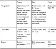
Features of valves of various modifications
The same tasks can be performed by various types of valves, characterized by different principles of valve design. Thus, according to the valve principle, the following main types of pipeline fittings are distinguished: valves, gate valves, faucets, dampers, hose valves, diaphragm valves, level, flow and pressure regulators.
The wedge valve is intended only to block the flow of the working substance; it cannot be used to regulate the pressure.
Valves are an integral part of the water supply system. There are different types of valves, each of which has its own characteristics, advantages and weaknesses.
Functional purpose
Depending on the type of product, it can be used to perform various functions:
- as a regulator of the flow of the working environment;
- as pipeline shut-off valves;
- as pipeline shut-off and control valves.
The main purpose of valves is their use as shut-off valves - devices necessary to shut off the flow of a working medium with a certain degree of tightness.
Their similar use allows for discrete (two-position) regulation of the flow of the working medium.
IN in some cases Short-term use of valves is allowed to perform the functions of shut-off and control valves.
Return to contents
Structural features of valves

Diagram of the main elements of the valve.
Each type of valve differs from other types of products according to a number of criteria. Depending on the design of the valve, designs are divided into parallel and wedge.
The difference between wedge modifications is that their sealing rings are located at a certain angle, forming a wedge, while for parallel valves such rings are located parallel to each other.
Wedge models are made with a solid (elastic or rigid) wedge or a double-disk composite wedge formed by 2 disks located at a certain angle to each other.
A parallel valve can have a valve in the form of 1 sheet or disk, or in the form of 2 disks with a spacer spring or spacer wedge located between them.
Parallel valves are made of cast iron. They are used as control and shut-off valves for steam, gases and water. The fittings are connected to the pipeline using flanges and bolts. Parallel valves with rising stems are shut-off valves and can at the same time be used as a gate to regulate the volume of water supplied. They are installed on pipelines with a diameter of at least 50 mm.
Shut-off valves can be with a non-retractable (rotating) or retractable spindle. In the first case, when opening and closing the valve, the spindle performs only rotational movement. The running thread is in contact with the working medium. In the second case, when opening and closing the valve, the spindle makes a translational movement. The running thread and nut are located outside the valve cavity.
The shut-off valves are controlled using an electric or manual drive. On large-diameter manually operated valves, a gearbox with spur, bevel or worm gears is used to reduce the required force on the manual drive flywheels.
As a rule, such shut-off valves are made full bore, that is, the diameter of the valve passage is almost the same as the diameter of the pipeline. In some cases, to reduce dimensions and weight, reduce moments and forces required to control shut-off valves, “bell-shaped” (narrowed) valves are used.
Return to contents
Structural modifications and main types of valves

Gate valve drive diagram.
There are valves various types. Thus, according to the type of valve, the following shut-off valves are distinguished:
- with a wedge locking element (wedge);
- with parallel locking element (gate);
- with elastic deformation of the valve channel under the working medium (hose).
In turn, wedge modifications can be with a composite wedge, with an elastic wedge and with a solid wedge.
Gate valves are a type of shut-off valve in which the sealing surfaces of the valve elements are located parallel to each other. Such fittings also have a number of modifications. Thus, single-disc gate models are equipped with 1 disk, which is pressed by the sealing surface to the surface of the housing seat. In the center of the disk there is a hinge, through which force is transferred from the rod to the disk. The compression can be carried out using wedge spacers installed in the housing.
Double-disc gate products can be either with wedge or spring spacers.
According to the method of movement of the gate valve, shut-off valves can be rotary type or reciprocating type. In gate valves, sealing along the gate is carried out using spring-loaded movable seats. There are modifications of the rotary type, which are equipped with 2 fixed disks with holes, between which a movable disk is placed. When this disk is rotated, the working medium is blocked.
The use of elastic elements guarantees the necessary fit of the contacting surfaces of the disks.
Depending on the type of body shaping, the product can be:
- cast;
- welded;
- forged or stamped;
- combined.

Scheme of types of valves.
When choosing a method for manufacturing the product body, the following factors are taken into account:
- production program and technological capabilities of product production;
- resistance of the shut-off valve body to the working environment;
- restrictions depending on the conditions of use of the product (temperature, pressure, corrosion resistance, etc.);
- quality characteristics of the material used to make the case.
In the manufacture of metal locking structures, the main type of shaping of the product body is casting. But with high requirements for strength, stamping, forging, or a combined method of manufacturing the body are more preferable.
There are other classifications of locking products. So, according to the type of sealing of moving parts, they are divided into:
- self-sealing;
- bellows;
- stuffing box
Stuffing box valves - tightness of moving parts (rod, spindle) in relation to external environment is ensured by a gland seal. In bellows modifications, the tightness of the moving parts is ensured using a bellows - an elastic corrugated shell that maintains strength and density under high-cycle deformations.
Depending on the nature of the transmission of control force to the valve gate, there are:
- with linear drive;
- with a rotary drive.
By type of control:
- from the work environment;
- from hydraulic drive;
- from a pneumatic drive;
- from electric drive;
- manual via gearbox;
- manual from the flywheel.
Federal Agency for Education
State educational institution of higher education
vocational education
"Ufa State Petroleum Technical University"
Department: “Transport and storage of oil and gas”
Test
on the topic: “Types of shut-off valves, their purpose and design”
Completed by: student of group GRz-07-02
Politaev M.A.
Checked by: teacher
Fazletdinov R.A.
Shut-off valves - designed to completely shut off the flow of the working medium in the pipeline and start the medium depending on the requirements of the technological process (open-close cycle). This includes gate valves, taps, shut-off valves, and butterfly valves. The main purpose of shut-off and control valves is to shut off the flow of the working medium through the pipeline and let the medium in again, as well as to ensure the necessary tightness. The pipeline fittings plant monitors the quality of its products. The fittings are installed on high and low pressure pipelines, units and vessels. Shut-off valves are designed to control: water, gaseous, vapor, gas-liquid mass by changing the area of the diameter of the opening. It must ensure reliable and complete overlap of the flow area. In principle, it should provide only two states - open or closed - and may not be intended for operation in an intermediate position of the working body.
According to their functional purpose, pipeline fittings are divided into the following main classes:
Shut-off valve - designed to shut off the flow of the working medium with a certain tightness;
Regulating - designed to regulate flow by changing the amount of working medium flowing through the pipeline. The control valves are controlled from an external energy source;
Distribution - designed to distribute the flow of the working medium in certain directions or to mix flows;
Safety - designed to automatically protect equipment and pipelines from unacceptable excess pressure by discharging excess working fluid., protective (cut-off) designed to automatically protect equipment and pipelines from unacceptable or unforeseen technological process changes in parameters or direction of flow of the working fluid, as well as to shut off the flow .
Phase separation - designed for automatic separation of working media depending on their phase and condition. These include steam traps, air vents and oil separators.
A gate valve is one of the shut-off valve devices. Here, unlike taps, the shut-off element does not perform a rotational movement, but a reciprocating one. The movement of the locking element occurs perpendicular to the movement of the liquid.
Chronologically, valves appeared as one of the first devices to shut off water flow. This is due to their sufficient simplicity and unpretentiousness in operation and repair. At present, due to the rapid development of technology and technological processes, valves are increasingly being replaced when laying pipelines by water shut-off devices with a circular movement of the actuator. Gate valves, like shut-off valves, are used mainly in two modes: open and closed, i.e. when the shut-off element is in its extreme positions. When using a valve in an intermediate position, its working surface is destroyed due to vibration caused by high-frequency movement of the actuator along and across the flow of liquid as it moves through the pipeline. The fastening elements of the actuator also become loose. As a result, the valve fails ahead of schedule.
Valves are divided into several types. Wedge, parallel, with retractable and non-retractable stem. They are used at pressures from 2 to 200 atmospheres. Nominal diameter from 8 mm to 2 m.
Figure 1 Gate valve ZMS-65-14 K1 HL (Baku)
Table 1 Technical characteristics of the valve ZMS-65-14 K1 HL
| Specifications |
|
| 14 (140) | |
| 2.Nominal bore, mm | 65 |
| 393 (120) | |
| 4. Valve design | K1 |
| 5. Gate valve | Cast housing |
| 6. Established service life of the ZMS | At least 12-15 years |
| 7. Gate valve design | Non-retractable spindle |
| 8. Replacing cuffs | Under pressure |
Christmas tree equipment is designed for sealing wellheads, monitoring and regulating their operating mode, as well as for carrying out various technological operations in moderate and cold macroclimatic regions for environments containing CO2, H2S, and formation water. Assembled according to tee and cross type schemes in accordance with GOST 13846 - 84.
The following designations are adopted in the code for the Christmas tree fixtures: AF – Christmas tree fittings; design according to GOST 13846 – 84 schemes; a – double-row concentric suspension of lifting pipes; K – suspension of the lifting string on the thread of the pipe head sub (the letter is not written on the coupling suspension); E – for operating wells with ESP; B – method of valve control (remote and automatic); the first number is the nominal diameter of the barrel and side strings in mm; the second number is the working pressure; HL – climatic version for cold areas; corrosion resistance version: K1 – for environments containing CO2 up to 6%; K2 – for environments containing CO2 up to 6%; K3 – the same, H2S and CO2 up to 25%; K2I - for Christmas tree equipment made of low-alloy and low-carbon steel, using an inhibitor in the well.
The fittings include a pipe head, a fountain tree, shut-off devices with manual and pneumatic control, and chokes.
The pipe head is designed for hanging one or two rows of tubing, sealing them, as well as for performing technological operations during the development, operation and repair of a well.
The riser pipe columns are suspended on threads and coupling suspensions.
Hanging of columns on the thread is carried out: with a single-row elevator - on the thread of the stem coil; with a two-row elevator: the inner column is on the thread of the stem coil, the outer column is on the thread of the tee (cross) of the pipe head.
Hanging of columns on a coupling suspension is carried out: with a single-row elevator - on a coupling in the crosspiece of the pipe head; with a two-row elevator: internal - on the coupling in the tee of the pipe head, external - on the coupling in the cross.

Figure 2 Christmas tree fittings AFK 1 E65x21M K1 HL
(for ESP, RPM and flowing wells)
The tree is designed to direct well production to the flow line for regulating the operating mode, for installing special devices when lowering downhole tools or pigs to clean paraffin from pipes, measuring pressure and temperature of the medium, as well as for carrying out some technological operations.
Continuous plug valves and direct-flow valves with forced or automatic supply of lubricant are used as shut-off devices for Christmas tree fittings. They are designed to cover flow holes in Xmas trees and wellhead equipment.
Table 2 Technical characteristics of the Christmas tree fittings AFK 1 E65x21M K1 HL
| Specifications |
|
| 1. Working pressure, MPa (kg/cm2) | 21 (210) |
| 2. Conditional bore, mm: trunk / side branches | 65/65 |
| 3. Temperature of the working environment is not more than K (C 0) | 393 (120) |
| 4. Hanging pipe | NKT-73 GOST 633-80 |
| 5. Type of locking device | Gate valve ZMS 65x21 |
| 6. Ensuring the replacement of cuffs in the MZS under pressure | 21 MPa |
| 7. Tee | Cast housing |
| 8. Gate valve | Cast housing |
| 9. Cross | Cast/forged body |
| 10. Adapter | Cast/forged body |
| Established service life of fittings and protective structures | At least 12-15 years |
To regulate the operating mode, adjustable or non-adjustable throttles with a replaceable bushing made of wear-resistant material are installed on the side strings of the tree.
Christmas tree fittings are classified according to their design and strength characteristics:
Working pressure (7, 14, 21, 35, 70, 105 MPa);
Execution scheme (6 schemes);
The number of rows of pipes lowered into the well;
Designs of locking devices;
The dimensions of the flow section along the wellbore (50-150 mm) and side branches (50-100 mm).
All Christmas trees are used with column heads OOK1 10"" ´ 9 5/8 ´ 6 5/8 - 210 or column heads designed by TsNIL "" GANG "".
Column heads, like casing pipes, are an integral part of the well design as an engineering structure. They are designed to suspend the next casing string, seal and control the pressure in the annular space between adjacent pipe strings.

Figure 3 Column head piping OKK1-35 K1 HL
The design of the column head, Christmas tree fittings, and their piping schemes must ensure optimal well operating conditions, sealing of the pipe, annular and annular spaces, the possibility of technological operations at the well, deep research, sampling and control of wellhead pressure and temperature.
The operating conditions of the casing head are quite complex: the load from the weight of the casing strings can exceed several hundred kilonewtons in deep wells. The elements of the column head also perceive the pressure of the medium in contact with them. Violation of the reliability of the column head inevitably leads to serious accidents and damage environment, and in some cases can cause fires, explosions, and accidents.

Figure 4 Rotary shutter
A valve is an element of pipeline shut-off valves, where the regulating (shut-off) element rotates around an axis that is not its own axis. The most common type of this type of pipeline valve is a butterfly valve, in which the control element is made in the form of a disk.
Depending on the type of ensuring the tightness of shutting off the flow of liquid, butterfly valves can be with a metal-to-metal seal, with a soft seat seal, or with a Teflon coating of the shutting parts of the valve. Depending on the type of connection to the water (pipe) wire system, the valves come with flanges for welding and for threaded connections.
The shutter can be controlled, depending on the force required to bring its moving part into working position, using a simple handle, through a gearbox, through a pneumatic drive or electric. The material and design of the valve must be such that it can work for the required period not only to open and close the substance passing through it, but also to regulate the volume passing through. To do this, the bolt handle is most often made with a lock, which allows you to lock the handle in various angular positions.
Such operational properties of valves as convenience and ease of installation and replacement of sealing elements, sufficient durability (up to 100 thousand openings and closures), and relatively low cost have led to their widespread use in the pipeline industry.

Figure 5 Stopcock
Shut-off valve is one of the types of shut-off equipment. It can be made of various materials: steel, brass, some kind of plastic, etc. But they all have the same device - a body and a locking element. The shut-off element can be made in the form of a cylinder (cylindrical valve) or in the form of a ball (ball valve). Less often in everyday life you can find a faucet with a conical shut-off device.
In terms of performance, shut-off valves can be full bore or semi bore. Half-bore valve - if the hole to be closed is smaller in diameter than the diameter of the pipes connected to the inlet and outlet. And, accordingly, full bore - when it is the same.
The main task of a stopcock is to stop the flow of liquid passing through it. That is, it has two working positions - open and closed. It is clear that if the faucet handle is turned not by 90 degrees, but, say, by 45, then the flow of passing liquid can be reduced, roughly speaking, by 2 times. Thus, by smoothly changing the angle of rotation of the handle, you can smoothly change the passing flow. However, this is not recommended, because depending on the pressure and composition of the liquid, the shut-off valve may be damaged, this is especially true for the sharp edges of the valve structure, which can wear off, as a result of which, when completely closed, the liquid may continue to ooze out at the outlet of the valve.
Shut-off valves are used both in industry (for transporting water, oil products, gas) and in everyday life, for shutting off if necessary various parts water supply

Figure 6 Valve
Valves. This is another class of shut-off valve devices. Here the locking element is located on the spindle. The rotational movement in one direction or another of the spindle (using a simple flywheel or some devices) is converted into a reciprocating movement of the locking element, which regulates the flow of liquid passing through it. The spindle is rotated either manually (if the force is small) or using some kind of electric (hydraulic) motor.
The mass consumer is most familiar with this type of shut-off valves in everyday life, since various modifications of valves can be found in any apartment, in a suburban area, in various kinds of public premises, etc.
The most common type of valve is a straight-through valve, which is installed on straight sections of the pipeline. The main disadvantage is the fairly high hydraulic resistance and, as a consequence, the presence of a zone of stagnation of liquid in the area where such a valve is installed. A direct-flow valve, used in those places of the pipeline where a decrease in the liquid flow at the valve outlet is not allowed, does not have this drawback.
Also, the most common types of valves include angle valves (connects two mutually perpendicular parts of the pipeline) and mixing valves (they mix two liquid flows in order, for example, to maintain a given temperature).
Figure 7 Combined multifunctional valve type KKM
The combined multifunctional valve KKM-89x21 is designed for installation instead of a check valve in the tubing string assembly for oil production using electric centrifugal pumps (ESP)
Table 3 Technical characteristics of KKM
| Specifications | KKM-89x21 |
| ESP operating capacity for valve operation, m 3 /day | 80…800 |
| Outer diameter, mm | 89 |
| Length, mm, no more | 370 |
| Column lifting speed, no more, m/s | 0,3 |
| Nominal diameter of the passage hole, mm | 32 |
| Connecting thread according to GOST 633-80 | smooth tubing 73 |
| Weight, kg, no more | 10 |
| Working pressure, MPa | 21 |
In pipeline fittings, valves act as a kind of sensors combined with an actuator.
The main type is safety valves, which automatically release (into the atmosphere or into special containers) excess liquid or gas (steam) from a pipeline when a pressure is formed in it that exceeds the permissible technical parameters, thereby preventing a pipeline failure. According to the type of actuator, they can be spring and lever-load.
Regulating, bypass, distribution, mixing, and shut-off valves are also used, the purpose of which is easy to determine from their name.
Shut-off valves stop the flow of liquid or gas into the pipeline, starting from some section of it, when its flow is unacceptable (for example, when a pipe ruptures).
The bypass valve maintains a given pressure in a certain section of the pipeline circuit by partially opening and bypassing excess liquid or gas to another branch of the pipeline.
Distribution valves (three-way or multi-way) distribute flows of the working fluid into different sections of the pipeline, often from a control panel, and therefore they often have an electromagnetic drive.
Mixing valves are used if it is necessary to mix different media that have both different temperatures and different compositions. Such valves are required to maintain permanent staff or temperature (or both).
Control valves. Their task is to regulate the flow of the medium flowing through the pipeline (liquid, gas). They are most often controlled from an external energy source.
Bibliography
1. Petroleum Production Engineer's Handbook
2. Shurov V.A. “Engineering and technology of oil production” M. Nedra, 1983
3. Boyko V.S. “Development and operation of oil fields” M. Nedra, 1990.
4. Catalogs of oil production equipment manufacturers
Shelters from being crushed by vehicles. The greatest depth from the ground surface to the top of the channel slab is in any case taken to be at least 0.5 m. Classification, advantages and disadvantages, scope of application of flanged connections of pipelines and fittings Flanges are used for connection to various flanged fittings. Flanges are selected according to nominal diameters and pressures for which...


Gas-oil mixture rising to the mouth. The flowing method of operating oil wells is the most economical and profitable. By choosing this method of operation as the topic of my diploma and clearly demonstrating a model of a cross-type fountain fixture, I will consolidate my knowledge and also provide a training room for the technical school visual aid. The layout model of a cross-type fountain fixture is intended as...


... ; prevent accidental falls of radiator stoves; To roll up the threaded connections of the riser floors, have pipe wrenches corresponding to the diameter of the pipes being rolled up. Upon completion of installation, the installed heating system is subjected to testing, which is a very responsible and unsafe operation. The test must be carried out in the presence of the workman (master). IN...
Shut-off valves for pipelines are a means of dividing a pipeline network into separate local sections and regulating the pressure in them depending on their purpose.
This equipment is designed to completely close/open the flow of liquids of various types in the pipeline in accordance with the requirements of technological processes. Such devices include shut-off valves, gate valves, butterfly valves and taps. In turn, shut-off and control valves play the role of a flow regulator and create a tightness in the pipeline environment.
Shut-off valves of all types are intended for use in the following environments:
- liquid and gas-liquid;
- water;
- vaporous.
For the most part, such equipment is designed only to operate in two positions: “open” or “closed” and, most often, are not used in intermediate positions.
According to their purpose, fittings are divided into the following types:
- shut-off valve - to block the flow of the transported medium with the main condition - tightness;
- regulating - to establish a certain flow rate of the working medium by changing the nominal cross-section of the pipeline, as a rule, it is controlled by an independent energy source;
- distribution - division of the flow in the necessary directions, as well as for mixing different flows;
- safety – to prevent exceeding the permissible parameters of pipelines and vessels in terms of pressure by discharging the pumped products up to stopping the flow;
- phase separation - used to separate the product into various fractions and states, these include oil separators, condensate and moisture drainers.
The use of shut-off valves in sewerage systems is associated with the need to disconnect individual sections for repairs.
For pipelines
To be an effective means of transportation, product pumping is carried out over long distances at high pressure and at high speed. Therefore, special requirements are imposed on the selection of pipes and shut-off valves - gate valves, valves, butterfly valves.
It is selected in accordance with technical standards, design pressure, viscosity of the medium, differences in internal and external temperatures. The degree of pumping automation also matters.
In main water supply systems, the pumped liquid always contains a certain amount of aggressive components. Therefore, chemically resistant materials are used for fittings. These properties are fully possessed by cast iron, from which all types of shut-off valves for pipelines are made.
 They are used in high and low pressure pipelines and for pumping various media. The same material is most popular in the manufacture of pipeline fittings for oil pipelines.
Shut-off valves with sizes ranging from 8 to 2000 millimeters are used on main pipelines.
The valves are controlled manually using flywheels, and in hard-to-reach places - using an electric drive remotely.
Most cast iron valves are designed with flanged mechanisms and can be produced in various designs:
- Gate valves - with a movable or fixed rod;
, in which there is a flat gate with a hole corresponding to the size of the pipe. Two types of drive are used for control: manual for units located in an accessible place, and remote if the valve is installed in an enclosed space.
The manual drive consists of a handle in the form of a steering wheel, a screw pair and a rod attached to the gate. When the handle rotates, the screw pair converts the rotational motion into translational motion, which through the rod drives the gate in the desired direction. When the hole in it coincides with the hole in the pipe, the flow of liquid resumes.
- Wedge valves are a highly efficient type of shut-off valve for pipelines. The shape of the locking element allows for maximum sealing between the lock and the seat, which increases the quality of the closure.

Lifting the valve ensures that the wedge moves relative to the seat, as a result of which its hole is aligned with the hole in the stationary part, ensuring the passage of the working medium. Rotation can be done manually or using remote control.
- Parallel.
Such devices are designed to operate at pressures of 2 - 200
atmospheres

The working medium and the locking elements of the device in the form of two plates are located in the chamber. The valve plates are attached to the actuator rod. When it rotates, they open, allowing water or steam to flow through the pipeline.
All presented valves have a number of common parameters, including:
- Connection to the product pipeline is made using flanges, couplings or welding.
- Valves are not used to regulate the pressure in the pipeline, but only close or open it in extreme positions.
- Gate valve bodies are made of cast iron, less often - of steel.
- All types of these fittings use sealing devices made of rubber, paronite, cardboard, etc.
- Depending on the availability of the device, a manual drive in the form of a flywheel or remote control using an electric drive is used.
Flanged shut-off valves for pipelines are used not only in water supply networks, but also when pumping petroleum products or other liquid media.
In distribution networks on water supply pipelines of DN100 or less, valves and taps with coupling connections are often used. Such devices are smaller in size and more technologically advanced to install. Connections are made by screwing onto the thread of the mating part.
The tightness of such a joint is ensured by the use of various sealants: flax fiber, FUM tape (fluoroplastic sealing material), sealing cords and special-purpose silicone sealant. This connection is less reliable than a flange connection, but eliminating leaks is faster and easier.

Shut-off coupling valves for pipelines are used on intra-house distribution networks with sizes less than DN 50 and a pipeline pressure of 0.6 atmospheres or more.
Water shut-off valves for distribution networks
 Such products various types and destinations are intended to deliver water from the supply tank to end point consumption. Its main purpose is to close or open the flow of liquid in a pipeline, as well as regulate pressure in the network. Simply put, any of these mechanisms, be it a tap or a valve, allows you to cut off or restore the water supply.
The design of the shut-off valve is quite simple. The basis is a cast iron or brass pipe. A valve is inserted into it, which can partially or completely block the lumen in the pipe, which leads to a change in pressure in the pipeline or a cessation of flow. The mechanism is controlled using a lever tap of any shape.
Functional purpose of devices
Fittings for the water supply network are installed not only in every house, but also in every apartment. It serves to regulate the pressure in the internal water supply system and distribute water throughout all rooms of the apartment, where it is provided for by the project.
Watch the video
Such devices are also installed in industrial buildings and premises where the use of water is provided for by production technology, as well as for sanitary needs. For this purpose, pipes made of special materials different from those used in residential construction are used.
Shut-off valves for water supply are functionally designed to lock liquid in a pipe and, if necessary, supply it to its destination in the required quantity.
The material for the manufacture of locking mechanisms can be various substances, but most often they are:
- Cast iron of various modifications.
- Brass.
- Stainless steel is capable of painlessly passing chemically active liquids, which are also often pumped through pipelines.
About the advantages and disadvantages of various classifications of devices
Thanks to its high performance and aesthetic appearance, valves made of brass or stainless steel are the most popular nowadays. Such products in the water supply network can last up to one and a half decades.
Despite this, research to improve the durability of water fittings using new materials is ongoing. As a result, devices made of polymer materials have appeared that can be used indefinitely for a long time, if disloyal methods of mechanical influence are not applied to them.
Watch video - classification and types
Otherwise, at the junction with various materials wear will not be the same. And the overall service life of the system is determined by the material that wears out the most.
One of the advantages of plastic water pipes is the fact that they do not have threaded connections. The elements are joined by soldering using special equipment or using adhesives. Such connections are as reliable as possible and can only be broken using brute force.
For main water networks, polyethylene pipes measuring 820 - 1020 millimeters are mainly used. They use plastic fittings for water supply systems. Such pipes can easily withstand the pressure accepted for water, in most cases no more than 20 atmospheres.
Metal pipes are connected with the same fittings. But, since threaded connections are less reliable, sealing materials and sealants must be used.
Let's look at the types and classifications
There are many designs of valves and taps for water supply. The most popular of them are:
- Cranes with crane axle box.

The flow of water through the pipe is blocked by twisting the rod by its action on the rubber gasket, which sits on the seat and blocks the passage. The weak point in this system is the gasket, which must be replaced periodically. Having a spare gasket in the house for such taps is an objective necessity. The bodies of such taps are made of brass, less often – of cast iron.
- Taps and valves with ceramic inserts
This design of water shut-off valves has already become common due to the high reliability of the access point.

Water is released from the pipe by turning the handle through an angle of about 180 degrees. In this case, the openings in the two ceramic plates are combined, and a passage for water from the water pipe is opened. Due to the high strength of the surface of the plates, their wear occurs very slowly, and the use of a supporting rubber gasket in the lower (fixed part) of the crane axle box ensures wear compensation and tightness of the connection. The parts of the crane box (and the crane itself) are made of brass.
- Ball Valves.

As a locking element in such devices, a ball made of brass with high quality surfaces. It is processed by polishing using diamond paste and subsequent nickel or chrome plating. The hole in the ball corresponds to the size of the passage. When the rod handle rotates, the ball rotates 90 degrees and closes/opens the hole. Wear-resistant Teflon rings are used as a seal. Not intended for pressure adjustment.
In addition to the above types of shut-off valves, many others are produced:
- taps for relieving air pockets in the heating system;
- emergency pressure relief valves installed on vessels;
- valves for regulating pressure in the internal water supply system.
Ball valves are used to shut off the pipeline in emergency situations.
Technology and production methods
The production of pipeline fittings is a complex technological process that includes a number of sequential actions that ensure the production of reliable and salable products.
Watch the video
The technology for the production of shut-off valves for pipelines involves the following actions:
- Marketing on the market of relevant products in order to determine the effective (sold) range of products.
- Design and survey work to create models and types of effective products both in terms of quality and manufacturing costs.
- Development of production technology, determination of the optimal composition of equipment.
- Development of methods for effective non-destructive quality control of products.
- Developing effective advertising for your products.
- Logistics and product sales.
The production technology of shut-off valves for pipelines can be presented as follows:
- Purchase of raw materials for production. Incoming quality control of raw materials and components.
- Production of blanks for the manufacture of fittings by casting from cast iron, brass and other suitable materials.
- Heat treatment of cast workpieces to give them the necessary mechanical properties.
- Mechanical processing of working surfaces to the required parameters of flatness and surface cleanliness. Turning of threaded connections.
- Application of protective coating by galvanic method. Nickel plating is usually used.
- Assembling water fittings using parts own production and components purchased through cooperation.
- Final quality control finished products and transfer of finished products to the warehouse. It should be noted that intermediate control operations during the manufacture of fittings are carried out after each technological step. For example, after casting and electroplating, ultrasonic testing is required to identify cavities and other discontinuities.
- Sales of finished products.
Enterprises that intend to sell their products abroad need to certify them according to ISO 9001. It is important that in accordance with the requirements of this standard, not only final result(products), but also the entire process of organizing production, starting from document flow.
Watch the video
Technical documentation
Production of shut-off valves for pipelines and oil pipelines in part general requirements regulated by GOST R 53673-2009. Operating rules and installation features are considered by a number of SNiPs in terms of relevant requirements.
Posts